Saturday, 25 October 2014

Boss GE-7 Equalizer, (Monte Allums) Noise Reduction Modification


Here are a few pictures to show the Monte Allums - Boss GE-7 Equalizer mod which can purchased from his website at a very reasonable cost.

Here's a link to his website.
http://www.monteallums.com/pedal_mods.html

Of course you don't have to buy a kit, in fact you could do your own research and purchase the parts yourself -  but for the price of one of Monte's kits it's not really worth the hassle; unless of course guitar pedals are your thing.


So here is the PCB.


PCB Marked with locations of the 4 Op-amps.


4 Op-amps replaced for special low noise versions.


7 Capacitors replaced; these reduce noise and enhance the clarity.


1 Capacitor left to replace and some of the removed parts


PCB board cleaned to remove flux residue and pen marks.


Some sheets of paper slipped behind the PCB board mask the surrounding area from over-spray of PCB lacquer.


Once I got the pedal back together I tested it out and I was very pleased with the results; I could hear a definite reduction of 'hiss', especially in the top EQ ranges !


Monday, 6 October 2014

LG FLATRON W2052TQ FAULT / PROBLEM (does not turn on, hissing sound, screen flicking)

This morning when I went to switch on my computer monitor it was completely dead!  the display which is a "LG FLATRON W2052TQ"  was bought probably around 6 years ago.

So the first thing I did was tested the socket end for a mains voltage, this was fine - so I disconnected all the cables and spent a few minutes doing some web searches; these turned up a common fault with the capacitors in the power supply.

Next I dismantled the monitor; so - out came the bezel; then a few little connectors and a flat-flex cable; then 4 screws and then I had complete access to the power supply.

I could see 2 swollen capacitors and another one which was suspect;  so I decided to replace 4 just to be sure;  next using solder-wick dipped in flux I removed the old ones cleanly, and then in went the new ones.

After a little struggle to get it all back together I switched it on and it powered up and worked fine.

It seems crappy that this monitor had it's power caps fail after just a few years for the sake of not spending a tiny bit more money on better parts.


Wouldn't power-up, no signs of life!


The power board


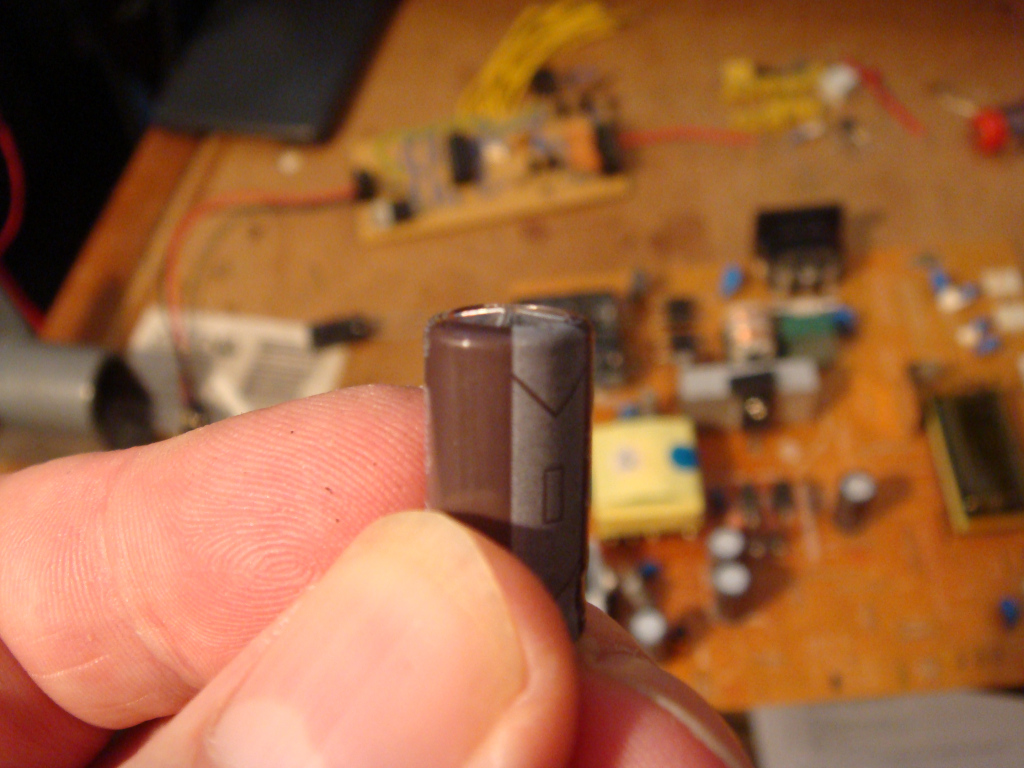
One of the swollen capacitors.


 Removed 4; replaced 2 of 4


Replaced 4 of 4. (as seen in the 2x2 arrangement)


Now works a treat!


STOP THE BUS!!

Well, it seems after I replaced the 4 duff caps it worked fine for good while but then I got some screen flicker and hiss;  so I cracked it open yet again and replaced another duff cap which appeared to have a very visible bulging of the top.


Not sure how long this display will last as there is some very noticeable heat discolouration of the underside PCB board under what looks to be the backlight inverter.

I'll probably soak test the display for a good few hours and see if anything else fails; but one thing is for sure,  I'm not holding my breath for this one!


[UPDATE]

After a few days the unit died yet again!!  I think possibly the inverter transformer had given up;  so i looked for a replacement board but I couldn't find one, so I dumped the monitor and bought a HP one instead.


Wednesday, 4 December 2013

Bad Trimmer Pot


The other day I was setting up one of my new controller boards; and part of that process involves turning the trimmers to their maximum anti-clockwise position.

Once the board was powered up, this one particular trimmer which was used to trim the LCD contrast didn't seem to make any difference when adjusted; So I knew instantly the trimmer was at fault so I just replaced it with another and it worked perfectly.


The problem seemed to be that when I initially quickly adjusted it to it's maximum anti-clockwise position, the wheel gear cog must have gone too far, and then wouldn't re-engage;  I've never experienced this before but might be something to bear in mind;  luckily for me the LCD contrast made the screen visible; but had it failed in the clock-wise direction of turn - the LCD would have been blank! and I would have certainly had to fire-up the scope to find out what was going on.

Below are a few pictures of the offending trimmer pot which I cracked open with the side-cutters;  I managed to break a leg off it in the process but interesting to see how it's constructed.


Thursday, 7 November 2013

Korg A5 Repair

I bought this from Ebay, and it was sold as Spares Repair.

After powering up there was no response from the unit; after checking the power rails there was no power getting to the 7805 5 volt regulator. I found that one of the input jack terminals had completely broke the copper track it was soldered on to.


I removed the solder from the bad pin; the broken track just fell away leaving the bare board around the pin.


I
I soldered on a wire link to bridge the gap where the track was missing.
Then I cleaned the main PCB board,  including all the switches and pots.


One of the switches showed a lot of corrosion; perhaps something was spilt onto the board through the stomp foot pedal at some point.

After I checked the switch it turned out to be faulty;  but luckily I had some old keyword switches lying around;  the keyword switch was a perfect replacement, and soldered directly in;  the only problem was - it was the wrong height!  so I ended up cutting a small piece off a spare rubber foot that had adhesive attached, and that seemed to do the trick very nicely!


So after that I put it all back together and powered it up it worked fine;  I noticed the input jack wasn't great, so I will replace that with some spare ones when I get a spare minute.


I found a spare minute to change both the guitar input jack and the output jack;  the input tab had broken, hence the bad connection, and the output had partially broke;  I also added some "hot-snot" glue to help reduce any jack movement.


Saturday, 31 August 2013

Low Cost 8 Channel Logic Analyser

!!! Since this was posted I've learned that these cheap logic analysers are basically copy-cat rip-off hardware labelled up to look like they are made Saleae;  these aren't by Saleae!  If you're looking for a decent low cost logic analyser with superb software check-out the proper Saleae ones.


Quite a small compact little unit. It's rather cheap looking but I wouldn't expect too much for the price.


Hooked up and ready to capture some data.


Capturing a short burst of I2C data from the uC to the 24LC512 chip.


This was my first experience of a capture of my I2C signal from my board;   it looks ok, although I can't pass much of a judgement on this unit until I've used it a bit more; but on first impressions - it looks pretty good value for money!

Wednesday, 14 August 2013

Basic Transistor Amplifier

The other day I decided to try and build a simple one transistor amplifier.


This is the circuit; and the transistor used was the BC546A.


I input a 20mV 10KHz sine wave test signal to the the input stage of the transistor amplifier.


This shows the original signal (top) and the amplified signal (bottom).
The input measured ~20mV and the output measured ~1.75V according to the scope.

Playing with a MAX6126 Voltage Reference


Recently I picked up some cheap MAX6126 chips from Ebay;  this is the Maxim blurb about them..

"Ultra-High-Precision, Ultra-Low-Noise, Series Voltage Reference Features 3ppm/°C (max) Temperature Coefficients and an Excellent ±0.02% (max) Initial Accuracy"
I created a simple layout and etched it on a board;  I should have added some caps as per the datasheet specifications and the long breadboard wires I suspect didn't help either!

Anyway when I applied some power and measured it with my recently calibrated bench meter it was really quite good;  the ambient temperature effected the readings slightly; as it showed ~2.048v when it was ~22°C - but if it was >22°C,  it tended to drift slightly below.


One thing it did prove; and that was that my other two DMM's that I suspected were slightly out - were indeed not as accurate as I had previously thought!

I have quite a few of these little chips left so I plan to see if I can create a more temperature stable version that I could use in another project.


A few days later I knocked up a little circuit on a breadboard that I plan to use to stabilize the voltage reference temperature; this might give me a reading that is more independent of the ambient room temperature.

The picture below shows the circuit setup on the lower part of the breadboard.  The LED is just hooked up as an indicator to show the cutoff point at which the transistor turns off.

What you can't see in the picture is me holding a hair dryer above the probe and thermistor; when the temperature reached about 41°C, the LED is beginning to switch-off.


At ~42°C the LED is very weakly lit;  this should give me a good starting point of the POT trim setting when I come to add the circuit to a little container.


I might keep the LED as an indicator on the final circuit;  but I plan to add some low ohm resistors and then drive them quite hard in order to generate some heat to warm a suitably small thermal chamber.