"Ultra-High-Precision, Ultra-Low-Noise, Series Voltage Reference Features 3ppm/°C (max) Temperature Coefficients and an Excellent ±0.02% (max) Initial Accuracy"
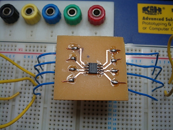
I created a simple layout and etched it on a board; I should have added some caps as per the datasheet specifications and the long breadboard wires I suspect didn't help either! Anyway when I applied some power and measured it with my recently calibrated bench meter it was really quite good; the ambient temperature effected the readings slightly; as it showed ~2.048v when it was ~22°C - but if it was >22°C, it tended to drift slightly below.

One thing it did prove; and that was that my other two DMM's that I suspected were slightly out - were indeed not as accurate as I had previously thought!
I have quite a few of these little chips left so I plan to see if I can create a more temperature stable version that I could use in another project.
A few days later I knocked up a little circuit on a breadboard that I plan to use to stabilize the voltage reference temperature; this might give me a reading that is more independent of the ambient room temperature.
The picture below shows the circuit setup on the lower part of the breadboard. The LED is just hooked up as an indicator to show the cutoff point at which the transistor turns off.
What you can't see in the picture is me holding a hair dryer above the probe and thermistor; when the temperature reached about 41°C, the LED is beginning to switch-off.

At ~42°C the LED is very weakly lit; this should give me a good starting point of the POT trim setting when I come to add the circuit to a little container.

I might keep the LED as an indicator on the final circuit; but I plan to add some low ohm resistors and then drive them quite hard in order to generate some heat to warm a suitably small thermal chamber.
No comments:
Post a Comment