Friday, 8 May 2015

Experiment - Simulating VR Signals


Over the last couple nights i've been looking at creating some simulated variable reluctance sensor signals.

The scope picture above shows the finished crank and phase signal waveforms being output from the bread-board circuit into channel 1 & 2 of the oscilloscope.

Although I was quite pleased with the results it would be nice to develop the project a little more perhaps when I have more time to do so.


The circuit consisted of a small PIC uC that outputs the desired shaped waveform into a 6 bit resistor ladder DAC;   then the DC signal was fed into a single operational amplifier which negatively offsets the DC signal to create a nice AC signal;  after that the signal is simply multiplexed to create both the crank and phase.


Once I had increased the total number of sample points in my waveform the shape started to look much better.


As you can see I used quite a lot of trimmer POTs;  I couldn't find any 2R values in my parts box, so instead of using two-of  the same value Rs,  I just used some cheap POTs I had.

Overall the circuit worked well.

Wednesday, 22 April 2015

First SMD Board

The other week I ordered some boards to be made up from a project i'm working on, this was my first SMD board so I wasn't sure how it would all turn out.

My original plan of attack was to turn a low cost toaster into a reflow oven;  but after I wrote the PIC code and then chewed it over for a day or two,  I realised that the 10 sec steps I was using would be too much and I might potentially damage some parts if it ramped up too quickly.

So I opted to use a cheap DIY hot air gun;  so I stuffed a DMM thermocouple into one of the board mounting holes and then using a timer, manually ramped the temperature keeping a close eye on the elapsed seconds and temperature on the DMM display.

Although this seemed to work fine, I think I'm going to rework the PIC code to use 3 sec steps instead, that way we shouldn't have any big ramp jumps. I much prefer the idea of putting a board into an oven and simply pressing a button, instead of waving a hot air gun over the board.

The results of the hot air gun can be seen below; although It worked ok I was a bit shy using the solder  paste so I should have used more;  in the end I had to apply more solder using the soldering iron to a couple resistors and capacitors;  but the ICs reflowed really nicely.


GenRad 1657 RLC Digibridge


For a while now I've been after a LCR meter but I wasn't sure what to get - now I'm always a sucker for older test gear; so, in the end I saw this on Ebay and decided to buy it.

It's quite an early piece of test equipment and apparently it was the first ever digital bridge meter.

As you can see from the PCB build style and the white ceramic 6503 processor with a date code of 1977 it's pretty vintage stuff.


I had to hook up some temporary 'croc' clips but I will order a proper set of kelvin clips when I get time.

It was sold with a display fault which turned out to be a problem with one of the 7 SEGMENT LED drivers; So I ordered some replacements and fitted them,  that seemed to fix the 7 SEGMENT fault but it was still glitchy for some reason;  I then noticed one of the range LEDs was dull,  so I replaced that too;  after that the display seemed to work fine!

I checked out the power supply; the 5V rail was slightly under but looking at the datasheet for the 5V regulator it was still within the manufacturers specifications.

I measured some CAPs, and it seemed great;  I then measured a few Inductors and it gave sensible results.

Below are a few pictures of the internals;  notice the very large smoothing CAPs on the power supply.


The above pic shows how the display board fits to the main board.


The above pic shows the white ceramic 6503 processor;   the other white package to the right of the CPU is a precision 25 Mhz crystal oscillator.

The two chips to the left of the CPU are ROMs;  one of the ROMs provide the code to run the CPU;  and the other provides the sinusoidal waveform data which is fed into a DAC.


The display board and the row of 9 driver chips;  one for each of 7 SEGMENT displays.


Whilst de-soldering and removing one of the LEDs, the LED literally fall apart.


Saturday, 25 October 2014

Boss GE-7 Equalizer, (Monte Allums) Noise Reduction Modification


Here are a few pictures to show the Monte Allums - Boss GE-7 Equalizer mod which can purchased from his website at a very reasonable cost.

Here's a link to his website.
http://www.monteallums.com/pedal_mods.html

Of course you don't have to buy a kit, in fact you could do your own research and purchase the parts yourself -  but for the price of one of Monte's kits it's not really worth the hassle; unless of course guitar pedals are your thing.


So here is the PCB.


PCB Marked with locations of the 4 Op-amps.


4 Op-amps replaced for special low noise versions.


7 Capacitors replaced; these reduce noise and enhance the clarity.


1 Capacitor left to replace and some of the removed parts


PCB board cleaned to remove flux residue and pen marks.


Some sheets of paper slipped behind the PCB board mask the surrounding area from over-spray of PCB lacquer.


Once I got the pedal back together I tested it out and I was very pleased with the results; I could hear a definite reduction of 'hiss', especially in the top EQ ranges !


Monday, 6 October 2014

LG FLATRON W2052TQ FAULT / PROBLEM (does not turn on, hissing sound, screen flicking)

This morning when I went to switch on my computer monitor it was completely dead!  the display which is a "LG FLATRON W2052TQ"  was bought probably around 6 years ago.

So the first thing I did was tested the socket end for a mains voltage, this was fine - so I disconnected all the cables and spent a few minutes doing some web searches; these turned up a common fault with the capacitors in the power supply.

Next I dismantled the monitor; so - out came the bezel; then a few little connectors and a flat-flex cable; then 4 screws and then I had complete access to the power supply.

I could see 2 swollen capacitors and another one which was suspect;  so I decided to replace 4 just to be sure;  next using solder-wick dipped in flux I removed the old ones cleanly, and then in went the new ones.

After a little struggle to get it all back together I switched it on and it powered up and worked fine.

It seems crappy that this monitor had it's power caps fail after just a few years for the sake of not spending a tiny bit more money on better parts.


Wouldn't power-up, no signs of life!


The power board
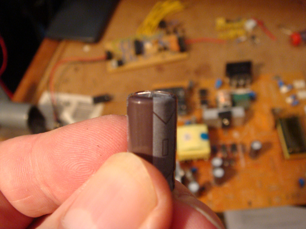


One of the swollen capacitors.


 Removed 4; replaced 2 of 4


Replaced 4 of 4. (as seen in the 2x2 arrangement)


Now works a treat!


STOP THE BUS!!

Well, it seems after I replaced the 4 duff caps it worked fine for good while but then I got some screen flicker and hiss;  so I cracked it open yet again and replaced another duff cap which appeared to have a very visible bulging of the top.


Not sure how long this display will last as there is some very noticeable heat discolouration of the underside PCB board under what looks to be the backlight inverter.

I'll probably soak test the display for a good few hours and see if anything else fails; but one thing is for sure,  I'm not holding my breath for this one!


[UPDATE]

After a few days the unit died yet again!!  I think possibly the inverter transformer had given up;  so i looked for a replacement board but I couldn't find one, so I dumped the monitor and bought a HP one instead.


Wednesday, 4 December 2013

Bad Trimmer Pot


The other day I was setting up one of my new controller boards; and part of that process involves turning the trimmers to their maximum anti-clockwise position.

Once the board was powered up, this one particular trimmer which was used to trim the LCD contrast didn't seem to make any difference when adjusted; So I knew instantly the trimmer was at fault so I just replaced it with another and it worked perfectly.


The problem seemed to be that when I initially quickly adjusted it to it's maximum anti-clockwise position, the wheel gear cog must have gone too far, and then wouldn't re-engage;  I've never experienced this before but might be something to bear in mind;  luckily for me the LCD contrast made the screen visible; but had it failed in the clock-wise direction of turn - the LCD would have been blank! and I would have certainly had to fire-up the scope to find out what was going on.

Below are a few pictures of the offending trimmer pot which I cracked open with the side-cutters;  I managed to break a leg off it in the process but interesting to see how it's constructed.


Thursday, 7 November 2013

Korg A5 Repair

I bought this from Ebay, and it was sold as Spares Repair.

After powering up there was no response from the unit; after checking the power rails there was no power getting to the 7805 5 volt regulator. I found that one of the input jack terminals had completely broke the copper track it was soldered on to.


I removed the solder from the bad pin; the broken track just fell away leaving the bare board around the pin.


I
I soldered on a wire link to bridge the gap where the track was missing.
Then I cleaned the main PCB board,  including all the switches and pots.


One of the switches showed a lot of corrosion; perhaps something was spilt onto the board through the stomp foot pedal at some point.

After I checked the switch it turned out to be faulty;  but luckily I had some old keyword switches lying around;  the keyword switch was a perfect replacement, and soldered directly in;  the only problem was - it was the wrong height!  so I ended up cutting a small piece off a spare rubber foot that had adhesive attached, and that seemed to do the trick very nicely!


So after that I put it all back together and powered it up it worked fine;  I noticed the input jack wasn't great, so I will replace that with some spare ones when I get a spare minute.


I found a spare minute to change both the guitar input jack and the output jack;  the input tab had broken, hence the bad connection, and the output had partially broke;  I also added some "hot-snot" glue to help reduce any jack movement.