After a bit of research I thought I'd go for the Easy-Vibe circuit that John Hollis published on his website, the website itself can be found here, easy-vibe.
My initial thoughts are I like the op-amp approach to the circuit rather than using the original transistor based approach as it makes for a smaller component count.
The Easy-Vibe seems to use LEDs to drive the LDRs; now, I'm not sure if that makes any significant difference in the sound when compared to using a light bulb - i'm guessing it does, but it might be interesting to try one against the other.
A few weeks ago I ordered most of the main parts so now I can actually get started with step 1 and that is to try and build up a working circuit on a breadboard.
...
So here is some progress I made last night, this part of the circuit is the power supply / pre-amp circuit.


...
I started work on the low frequency oscillator part of the circuit, or LFO as it's commonly referred to. And after a bit of tweaking, the LEDs are lighting up but they are not pulsating which is I believe what they should be doing. As far as I understand in the circuit there are 3 opamps to the LFO ; one is power to the LEDs based on the position of the DEPTH pot, and the other two are for the LFO . So i'm thinking I'm going to have to check my circuit in more detail and see if I've missed anything.

...
ok, so I fixed that; turned out one of the salvaged leds wasn't pushed into the breadboard properly.
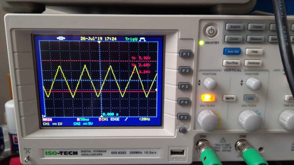
so now I get a nice triangle waveform on my scope, and the depth and rate seem to work as they should.
So, now all I need to do is build the 4 stage (phase shift?) part of the circuit.
...
ok, so this the final part of the circuit; the only tricky part here is coupling the LEDs with the LDRs and wrapping tape around each one; the Easyvibe build instructions suggest using heat-shrink tubing as a light shield, but I didn't have any to hand, so I just used black electrical tape.

I've given the 4 stages a quick look over and there were a couple of mistakes I missed, so I'll come back to this with fresh eyes later and make sure I haven't missed anything else before hooking it up for a proper sound test
...
After giving it another look over I did in fact miss a couple of wires; so after hooking it up to my guitar it worked :) the depth isn't quite there, prob about 45% of what it should be, by my ears anyway; but i'm sure that's just tweaks to the bias / photcells and leds to get that working right; which is what I plan to look at next.
...
Well, I tweaked the circuit slightly so I could use super bright white LEDs and then realised I had the pedal on the Chorus setting! so after I moved a wire across, it then burst into Univibe mode! lol Anyway - because I tweaked the circuit I need to re-add a LED bias part of the circuit back in.
...
21st July. So, I added another little change to the LED driver circuit, I think it sounds better - well to my ears anyway; I don't own or have ever used a Univibe so don't hold me to that! What I have tried to do is smooth the LED pulsating as much as possible to give more smoothness to the "whoshing" at slow speeds; this has to happen both with the ON and OFF parts of the cycle.
...
22rd July. I have been researching pedal cases and looking at designing a prototype PCB; the case I think I will go for is the Hammond series as they are really popular with pedal builders and it seems a no-brainer. The PCB is a bit more involved and will take a little more time to get right; I'd much prefer the jacks, leds and and pot on the pcb to make it less work less with soldering and trimming wires etc.
...

And I like how that sounds compared to the LEDs. I have also been looking at a different LFO circuit; so what I have done is I've used a microcontroller and a 12bit dac to generate a nice triangle wave which I hope to use to feed into the lamp driver circuit in order to drive the lamps; and that little circuit looks like this..


Pretty nice looking triangle wave.
So, now i'm going to add some POTs to this circuit so I can vary the Rate / Depth and Offset of the lamp driver waveform.
...
30th Aug. I have some more bulbs to try which were delivered recently; these are a slightly higher voltage than the mini bulbs so i'll need to work something out in order to power those.