Sunday, 7 November 2021

AEG Santo fridge freezer not getting cold

A few days ago we noticed the fridge part was not cold,  the freezer seemed fine.  So after watching a couple of Youtube's I decided to look at repairing it.


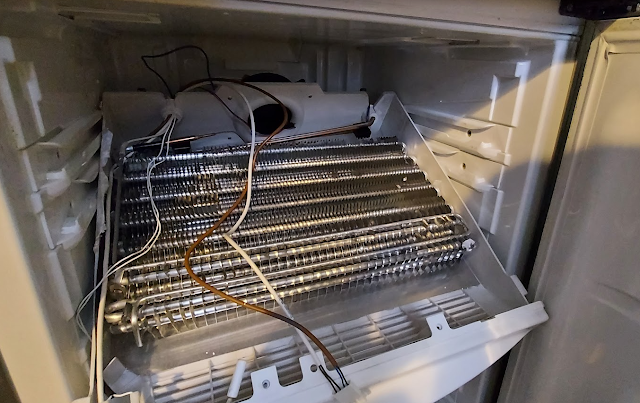
I went straight to the freezer part and looked at the evaporator battery and the defrost heater.
The heater measured 183 ohms.


The next thing I looked at were the heater overheat protection switches (see below),  they seemed to have continuity.


I was a bit confused I didn't find anything so I put it all back together and switched it back on;   to my surprise the fridge got cold,  so the ice build up must have restricted the cold air flow up to the fridge.

Then the fridge alarm kept going off every few hours again even though the fridge and freezer were nice and cold.

So I decided to look to look a the fridge side of things. So I stripped that all down.


Not much to it to be honest,  a PCB which takes input from the control buttons and freezer temp conrol and some leds.

As this PCB on it's own couldn't control the fridge I looked elsewhere;  and I found a box at the back of the fridge near the compressor.


After opening the box I found the brains of the fridge and oh dear!!


Something had popped!


Turned out to be one of the Triacs;  as there are only two Triacs on the PCB one must be for the compressor and the other for the defrost heater elements.


So I took off all the electrolytic capacitors and tested those with my ESR meter and 2 were iffy;  so I replaced those.

Now, I'm not convinced that the Triac would fail like that;  so I've ordered a new heater element so I can test the ohmns reading, as I think* my heater resistance reading is a bit too low.

I put the fridge back together and it's up and running in a basic way at least; I also left out the overheat protection sensors as it doesn't need those until I fit the new Triac and heater when they arrive next week.


To be continued!


Saturday, 8 June 2019

Building a Uni-Vibe type guitar effect pedal

I have always wanted one of these pedals so I thought it would be fun to try and build one;   this will be my first pedal build so i'm expecting to make a few mistakes along the way.

After a bit of research I thought I'd go for the Easy-Vibe circuit that John Hollis published on his website, the website itself can be found here, easy-vibe.

My initial thoughts are I like the op-amp approach to the circuit rather than using the original transistor based approach as it makes for a smaller component count.

The Easy-Vibe seems to use LEDs to drive the LDRs;  now, I'm not sure if that makes any significant difference in the sound when compared to using a light bulb - i'm guessing it does, but it might be interesting to try one against the other.

A few weeks ago I ordered most of the main parts so now I can actually get started with step 1 and that is to try and build up a working circuit on a breadboard.

...

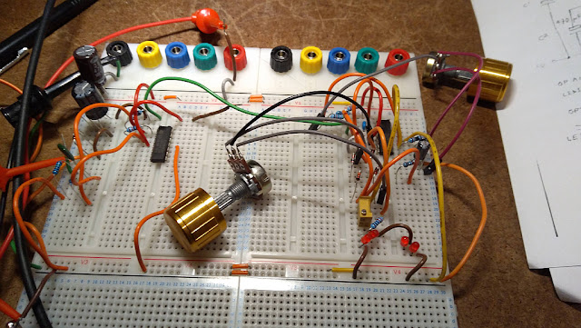
So here is some progress I made last night,  this part of the circuit is the power supply / pre-amp circuit.


 My breadboard is powered by my bench power supply set at 9V.

This is my simulated input signal from my signal generator, the frequency is set at ~600Hz @ 424 mVrms

And this is the preamp output sine wave, as viewed on my scope.


...

I started work on the low frequency oscillator part of the circuit, or LFO as it's commonly referred to.  And after a bit of tweaking,  the LEDs are lighting up but they are not pulsating which is I believe what they should be doing.  As far as I understand in the circuit there are 3 opamps to the LFO ; one is power to the LEDs based on the position of the DEPTH pot, and the other two are for the LFO .  So i'm thinking I'm going to have to check my circuit in more detail and see if I've missed anything.


...

ok, so I fixed that; turned out one of the salvaged leds wasn't pushed into the breadboard properly.
so now I get a nice triangle waveform on my scope, and the depth and rate seem to work as they should.


So, now all I need to do is build the 4 stage (phase shift?) part of the circuit.

...

ok, so this the final part of the circuit;  the only tricky part here is coupling the LEDs with the LDRs and wrapping tape around each one;  the Easyvibe build instructions suggest using heat-shrink tubing as a light shield, but I didn't have any to hand, so I just used black electrical tape.


I've given the 4 stages a quick look over and there were a couple of mistakes I missed, so I'll come back to this with fresh eyes later and make sure I haven't missed anything else before hooking it up for a proper sound test

...

After giving it another look over I did in fact miss a couple of wires;  so after hooking it up to my guitar it worked :)  the depth isn't quite there, prob about 45% of what it should be, by my ears anyway;   but i'm sure that's just tweaks to the bias / photcells and leds to get that working right;  which is what I plan to look at next.

...

Well, I tweaked the circuit slightly so I could use super bright white LEDs and then realised I had the pedal on the Chorus setting!  so after I moved a wire across, it then burst into Univibe mode! lol    Anyway - because I tweaked the circuit I need to re-add a LED bias part of the circuit back in.

...

21st July.   So, I added another little change to the LED driver circuit,  I think it sounds better - well to my ears anyway;  I don't own or have ever used a Univibe so don't hold me to that!   What I have tried to do is smooth the LED pulsating as much as possible to give more smoothness to the "whoshing" at slow speeds;  this has to happen both with the ON and OFF parts of the cycle.

...

22rd July.  I have been researching pedal cases and looking at designing a prototype PCB;  the case I think I will go for is the Hammond series as they are really popular with pedal builders and it seems a no-brainer.  The PCB is a bit more involved and will take a little more time to get right;  I'd much prefer the jacks,  leds and and pot on the pcb to make it less work less with soldering and trimming wires etc.

...

4th Aug.  ok.  so i've been playing around with using tiny bulbs in an arrangement like this..


And I like how that sounds compared to the LEDs.    I have also been looking at a different LFO circuit;  so what I have done is I've used a microcontroller and a 12bit dac to generate a nice triangle wave which I hope to use to feed into the lamp driver circuit in order to drive the lamps; and that little circuit looks like this..


Pretty nice looking triangle wave.


So, now i'm going to add some POTs to this circuit so I can vary the Rate / Depth and Offset of the lamp driver waveform.

...

30th Aug.  I have some more bulbs to try which were delivered recently;  these are a slightly higher voltage than the mini bulbs so i'll need to work something out in order to power those.


Saturday, 29 December 2018

Orb Retro Gaming Console - What's inside?


Orb Gaming System


The Orb Video Game System is a retro games console which is based on the Nintendo Family Computer, or "FAMICON" as it's more commonly referred to.

A quick look inside reveals, well - not that much actually!   there are 3 pcb's, one has the power socket and s-video adapters on it (top-most),  the center pcb has what must be main system on chip, which is under the black blob;  the bottom pcb has the console on /off and reset switches.


Orb Gaming System PCB


Moving on to the cartridge provided with the console which has the 400 games on..


The top-side pcb contains a single AS7C31025 which is 128K x 8 bit CMOS SRAM chip;  and then a chip blob;  I can only guess there is some sort of micro-controller of sorts under the blob which controls the game selection, so once a game is selected (i.e 1-400 ) from the initial boot-up menu, the cart controller will then grab the selected game from the Flash memory and then push that into the SRAM ready to be loaded up by the main system.


The reverse of the cart pcb showing the single S29GL512,  3v,  512 Mbit Flash Memory.


I picked this system up in an Xmas sale for £15,  but despite the really crappy cheap looking case etc, it is really quite enjoyable and probably very hackable!


Saturday, 13 October 2018

Solartron 7150 - Overload Issue

I already have a working one of these meters which I use all the time but I saw another one on eBay which was sold as spares fairly cheap (£35) which arrived yesterday;  so I thought I would try and repair it today.

When you power it on there are no indicated fault codes,  but the issue is whatever mode of measurement the meter is in the display will flash  "- OL -" or overload.


I checked the main voltage rails and they seem ok;  I briefly looked over the relays but I think I will need to look more closely at the analog input side of things.

...later that afternoon

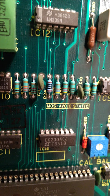
Well, after a shocking afternoon literally with this unit (lol don't ask!)   I managed to narrow it down;  so I just reheated a load of pins around the suspect area and it started working!   The calibration looks not too bad at all;  the sticker on it says the last calibration was 2016 so it should be good!

Btw, if your TIL117 chip is labeled IC307 then you have a later model 7150 (serials 300921 onwards), and if it's labeled IC306 then you have the older version;  there are some very subtle differences in the power rail circuit.


All in all very happy! :)


[later that afternoon... ;) ]


Well, the story didn't end there! it looks like I was somewhat premature in my celebrations!!, later that day it started glitching out again with the same issue!   I initially started to think it might be a component acting intermittently - that would have been a real nightmare to find and fix;  but what I found was after tapping the board in various places I found that it would fix itself, then fault again.

So, I carefully tapped each component and narrowed the issue down to near the front edge of the board;  after flexing the PCB very slightly one way I could make it work and by flexing it the other way it would fail;   so,  I started looking for any broken tracks on the board;  the PCB looked ok, so I started tapping each component,  then, all of a sudden I noticed the leg on a resistor had separated from the body - so I used my desoldering tool and took it out and replaced it for a metal film one, I tested a few resistors of the same value to get a better even closer match to the original one,  but the broken resistor was certainly the root cause of the overload issue.

I left the meter running most the evening and it was fine so I will leave it on for a few days to give it a bit of a soak test.


Sunday, 15 July 2018

ESP8266 - Success!

A while ago I purchased some ESP8266 wifi modules with a view to add wifi capabilities to a project I'm working on.

The ESP8266 modules are very commonly sold and can be picked up very cheaply.

The module itself looks like this.


These modules are 3.3 volts.  so I bought a USB to UART (3.3v)  module in order to experiment/test the ESP8266 from my computer.


The USB module looks like this once the ESP8266 is plugged into it.


Now there are heaps of examples of how you connect these up to Arduino boards or program them directly;  most of the Arduino examples use nice wrappers to get the ESP8266 up and running really quickly, but I wanted to use only the AT commands from my PIC microcontroller project to connect to the internet and pass data to a web server, and also get data back from the web server.

After a lot of messing about (I mean lots and lots of pain and hurt!) I found a nice workflow that worked for me;  that's not to say it will work with your module as these modules slightly vary between the firmware versions.

The process below describes using the ESP8266 with AT commands to pass data to a web server and then see the returned data from the web server.

For example, to send a web server the temperature read by your microcontroller.

eg.  http://myserver.com/mypage.aspx?t=120

What I did was create a c# console app to connect to the ESP8266 using the serial port and send it all the AT commands it needed to call a test aspx page on a web server which then returned some dummy JSON back to the module.


The first thing I did was use Realterm on the PC to connect to the ESP8266 using the 115000 baud and slow that down to 9600,  if you need to do this you can do that by sending the "AT+CIOBAUD=9600\r\n" command;  this is so when the ESP is talking to my project my microcontroller has more time to process the data.

The command sequence that worked for me was..

1. AT+RST\r\n
2. AT+CWMODE=1\r\n
3. AT+CIPMUX=0\r\n
4. AT+CIPSTART="TCP","X.X.X.X",80\r\n
5. AT+CIPSEND=N\r\n"
6. (GET command, see notes)
7. AT+CIPCLOSE\r\n

Step 4, when I tried initially using "http://myserver.com" all I got from the ESP8266  "400 Bad Request"  so, if you're having issues try the server IP address instead.

Step 5, N is the total number of bytes sent in the GET request;  the only gotcha is to count these properly, in c# you can count the length of a string using strMyString.Length,  this will cater for the "\r\n" characters in the string.  i.e "/r/n" is 4 characters but it's 2 bytes long.

Step 6,  this to me was the odd part, in that the GET request seemed to fail but work on some servers;  now, I think the issue was the GET request headers didn't match the requirement of the web server.

The headers that worked for me were..

            url_get =    "GET http://myserver.com/mypage.aspx?t=120 HTTP/1.1\r\n " +
                            "Host: myserver.com\r\n " +
                            "Connection: keep-alive\r\n " +
                            "Accept-Charset: ISO-8859-1,UTF-8;q=0.7,*;q=0.7\r\n" +
                            "Cache-Control: no-cache\r\n " +
                            "Accept-Language: de,en;q=0.7,en-us;q=0.3\r\n" +
                            "\r\n";


I may have over-cooked them a little but it seemed to work fine.;  you could play around and reduce them down to the minimum required by the web server.

Note: if you use HTTP/1.0 you don't require the "Host" header but if you use HTTP/1.1 you need to add that to your GET call.

Sending the commands it quite easy, but the tricky part is parsing the buffer of returned bytes in a way that triggers the next command in the sequence;  as you don't want to send the next command until the previous command has finished.   So, in the c# code I created a routine to check the serial read buffer for a particular string match;  the required strings I used for the step sequence above were..

Step 1.  If you use this prior to your calls you need to look for "WIFI GOT IP\r\n"
Step 2.  "OK\r\n"
Step 3.  "OK\r\n"
Step 4.  "OK\r\n"
Step 4.  "OK\r\n"
Step 5.  ">"  The > is the prompt for you to input the GET command string
Step 6.  Once the GET has completed you can look for the ":HTTP/1.1 200 OK" string, and within that buffer of bytes;  also within that buffer it will tell you how many bytes are returned;  this appears in the "+IPD," part of the string;  in my case, it looked like this..


Here you can see the string "+IPD,357" so this tells us there are 357 bytes in our buffer of returned bytes from the server, so you can then process through the buffer and pull out all the info you need.

I hope this helps anyone wanting to implement the ESP8266 in their project using only the AT commands.
Monday, 27 February 2017

Quadchek II 7564SA - Electrical Safety Compliance Analyzer

I bought this the other year on Ebay for a ridiculously cheap amount of money, but I didn't manage to get any output from it when I tried it,  so - I thought I'd take another look;  after a bit of googling I found out the unit required an interlock fitted to the back to enable the outputs to work;  not sure if this was retro-fitted sometime later as a safety feature? idk,  anyway, it turned out you can defeat this by simply shorting pins 4 & 5 on the input port;  so,  after doing this, the unit seemed to work perfectly;  the only issue was I don't have any the correct chunky HV test leads, so,  I had to rig some quick and dirty leads up to it in order to test it.

Below are 3 pics showing the testing of a 68V bi-directional TVS Diode.


Below is a pic showing a low ground bond test current being measured on my DMM.


Below are a few tear-down pics I took last year.


Thursday, 28 April 2016

Cropico ESC1 Electronic Standard Cell

A few days ago I managed to buy one of these for £5.50 on Ebay, it was was one the first zener diode replacements for the Weston cell,  but when I powered it up from my bench power supply it was dead!   so,  I cracked it open and after a while checking through the components I discovered one of the tantalum caps had shorted,  so I replaced that with an electrolytic one of the same value and when I powered-it-up,  it was working once again!.


The bad cap which was replaced!


The unit powers-up with 27 volts (or 18 x 1.5 volt C cells! ) and consumes ~16mA

From some measurements I took with my 7150 it seems that my 7150 has drifted quite a bit from the cal I had done a few years back;   the good thing is I can reasonable confirm this drift because the 1.0000v reference from my Time 2003S reads exactly the same on the 7150 as the Standard Cell.

The 7150 readings were..

Standard Cell  @ 1 volt
0.999815 volts

Time 2003S @ 1 volt
0.999815 volts

IDM305 DMM 1
0.9989 volts

IDM305 DMM2
0.9986 volts

Ambient was approx ~19.5 degrees C.


Inside the cover of the unit was a historic record of the measured Standard Cell voltages.


An identical unit was taken apart over on one of the popular electronics forums eevblog, the linked page also contains some useful PDFs.

http://www.eevblog.com/forum/metrology/cropico-esc1-electronic-standard-cell-a-look-inside/


This is another useful link to a site called "Johns Virtual Museum of Interesting Gadgets" where gives a short bit of information about the unit.

https://sites.google.com/site/johnhurll/home/cropico/ecs1-electronic-standard-cell